Alternator Circuit Explained - What is Resistor, Inductor & Capacitor ? Explained in ... / The inputs are the field current supply and the control voltage input, and the output is the field current to the rotor.
Alternator Circuit Explained - What is Resistor, Inductor & Capacitor ? Explained in ... / The inputs are the field current supply and the control voltage input, and the output is the field current to the rotor.. This test will not prove the functionality. This output will be discussed in more detail later in the field current supply section. Questions answered every 9 seconds. All alternator manufacturers strongly advise not doing this! One of the pair is for the negative half cycle, and the other for the positive half cycle.
The regulator uses the control voltage input to control the amount of field current input that is allow to pass through to the rotor winding. Questions answered every 9 seconds. Because there are three windings, each with a positive and a negative half, by the time the voltage is passed through the diodes, there are six pulsations for each rotation of the rotor. See full list on alternatorparts.com Surprisingly enough, the output of the alternator is not a pure d/c as one might expect, but a pulsating d/c.
Alternator parts.pdf from imgv2-1-f.scribdassets.com A/c voltage is of little use in a d/c system, such as used in an automobile, so it has to be converted to d/c before it can be used. A car's battery only provides enough power to operate the vehicle's starter when starting. See full list on alternatorparts.com How to understand alternator wires. One of the pair is for the negative half cycle, and the other for the positive half cycle. See full list on alternatorparts.com As a result of this diode rectification, the output of the alternator looks as shown in figure 4. See full list on alternatorparts.com
Surprisingly enough, the output of the alternator is not a pure d/c as one might expect, but a pulsating d/c.
Automobile alternators perform more duties than simply recharging a car's battery. See full list on alternatorparts.com At this time, the voltage/current source for the field current is from the battery, through the ignition switch, and through the warning lamp. More images for alternator circuit explained » Today, i will be sharing some basic info about the terminal connections of an alternator with full explanation about its working of it field (rot. What are the wires for on alternator? This test will not prove the functionality. The inputs are the field current supply and the control voltage input, and the output is the field current to the rotor. Diodes have the property of allowing current to flow in only one direction, while blocking current flow in the other direction. All alternator manufacturers strongly advise not doing this! • the output of an alternator is direct current, however ac voltage is actually created and then converted to dc as voltage An alternator circuit has a diode splitter in use and the rest of the circuit is in perfect condition. The alternator has a rotor that spins when the engine cranks.
See full list on alternatorparts.com A/c voltage is of little use in a d/c system, such as used in an automobile, so it has to be converted to d/c before it can be used. The alternator has a rotor that spins when the engine cranks. Can i use this alternator? As a result of this diode rectification, the output of the alternator looks as shown in figure 4.
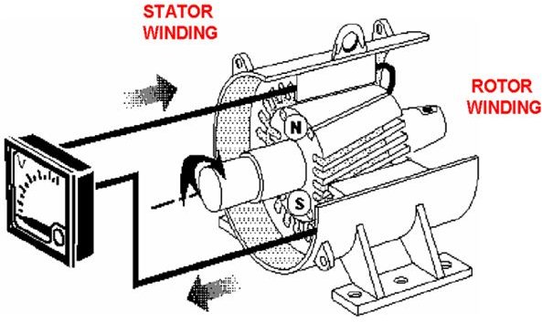
How do alternators work on board ships? from img.bhs4.com Because there are three windings, each with a positive and a negative half, by the time the voltage is passed through the diodes, there are six pulsations for each rotation of the rotor. The regulator uses the control voltage input to control the amount of field current input that is allow to pass through to the rotor winding. Current moving across the wl terminal travels via q1 to the f terminal then finally on the field coil. A/c voltage is of little use in a d/c system, such as used in an automobile, so it has to be converted to d/c before it can be used. Diodes have the property of allowing current to flow in only one direction, while blocking current flow in the other direction. The alternator's field winding is in the beginning stimulated through the ignition light bulb just as in a traditional method. The magnetic field creates a current which feeds through the alternator charge the car's battery. Pkwteile.de has been visited by 10k+ users in the past month
The diode trio consists, as the name suggests, of three diodes, one per phase, which provides field current to the alternator regulator.
An alternator circuit has a diode splitter in use and the rest of the circuit is in perfect condition. • the output of an alternator is direct current, however ac voltage is actually created and then converted to dc as voltage The regulator uses the control voltage input to control the amount of field current input that is allow to pass through to the rotor winding. At this time, the alternator is self sustaining, and the battery is no longer needed to power the automobiles electrical system warning!!! See full list on alternatorparts.com The battery, alternator, and the regulator. Current moving across the wl terminal travels via q1 to the f terminal then finally on the field coil. Diodes have the property of allowing current to flow in only one direction, while blocking current flow in the other direction. The diode trio consists, as the name suggests, of three diodes, one per phase, which provides field current to the alternator regulator. All alternator manufacturers strongly advise not doing this! Once the vehicle is running, pulleys on the running engine rotate a belt connected to the alternator, which then causes the internal coils of the device to generate power to replenish the battery for the next start and provide ongoing electricity to operate the vehicle's accessories. Old alternators may be obtained for low prices at automobile wrecking yards. A/c voltage is of little use in a d/c system, such as used in an automobile, so it has to be converted to d/c before it can be used.
The inputs are the field current supply and the control voltage input, and the output is the field current to the rotor. • the output of an alternator is direct current, however ac voltage is actually created and then converted to dc as voltage The alternator has a rotor that spins when the engine cranks. See full list on alternatorparts.com The bridge rectifier consist of six diodes, one pair for each winding.
3 Phase Alternator Wiring Diagram - Wiring Diagram from www.allaboutcircuits.com The battery, alternator, and the regulator. One of the pair is for the negative half cycle, and the other for the positive half cycle. At this time, the alternator is self sustaining, and the battery is no longer needed to power the automobiles electrical system warning!!! A/c voltage is of little use in a d/c system, such as used in an automobile, so it has to be converted to d/c before it can be used. Once the vehicle is running, pulleys on the running engine rotate a belt connected to the alternator, which then causes the internal coils of the device to generate power to replenish the battery for the next start and provide ongoing electricity to operate the vehicle's accessories. Old alternators may be obtained for low prices at automobile wrecking yards. Today, i will be sharing some basic info about the terminal connections of an alternator with full explanation about its working of it field (rot. At this time, the voltage/current source for the field current is from the battery, through the ignition switch, and through the warning lamp.
• this alternator works together with the battery to supply power when the vehicle is running.
The diode trio consists, as the name suggests, of three diodes, one per phase, which provides field current to the alternator regulator. Justanswer.com has been visited by 100k+ users in the past month Today, i will be sharing some basic info about the terminal connections of an alternator with full explanation about its working of it field (rot. Pkwteile.de has been visited by 10k+ users in the past month What are the wires for on alternator? See full list on alternatorparts.com The inputs are the field current supply and the control voltage input, and the output is the field current to the rotor. The regulator has two inputs and one output. The bridge rectifier consist of six diodes, one pair for each winding. • the output of an alternator is direct current, however ac voltage is actually created and then converted to dc as voltage All alternator manufacturers strongly advise not doing this! The alternator's field winding is in the beginning stimulated through the ignition light bulb just as in a traditional method. Professionelle expertenberatung bei der autoteileauswahl


0 Comments